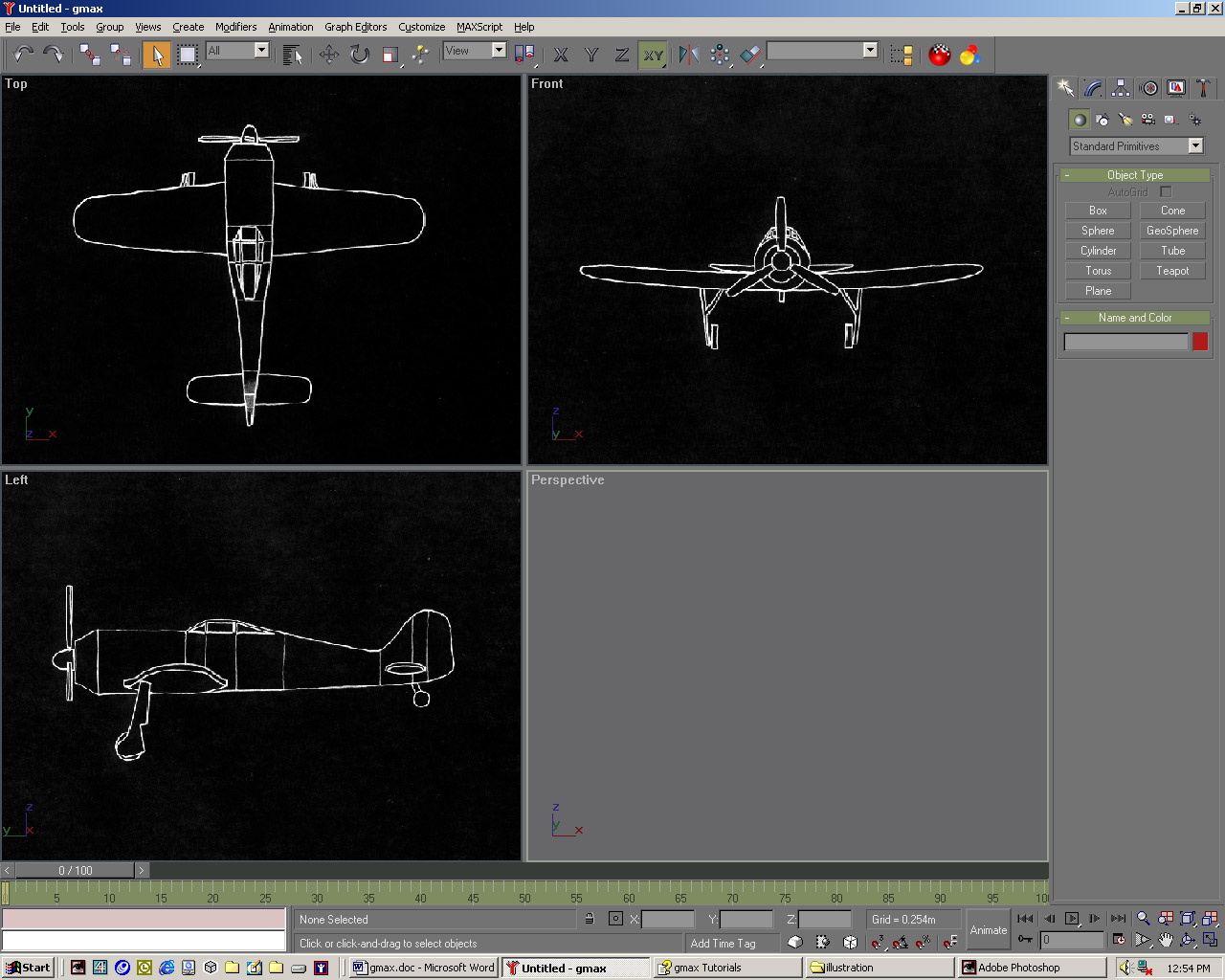
We'll begin by modelling the wings and tail, then move on to the more complex fuselage.
| 01 From the Customize menu, pick Units Setup and choose Metric. Right-click in the Top viewport and from the main menu bar select Views > Viewport Background. In the new dialogue hit the Files ... button and choose TopView.jpg. OK this and check Match Bitmap and Lock Zoom/Pan. Hit [G] to turn off the Grid in this viewport. Repeat for the Left and Front viewports. |
 |
| 02 Right-click in the Top viewport and in the right-hand create panel, within the Object Type rollout, click Box. Open the Keyboard Entry rollout and enter the following values: Length: 1.1m, Width: 5.0m: Height: 0.2m. Click the Create button. In the viewport navigation controls at the bottom-right corner of the interface, click 'Zoom Extents All'. |
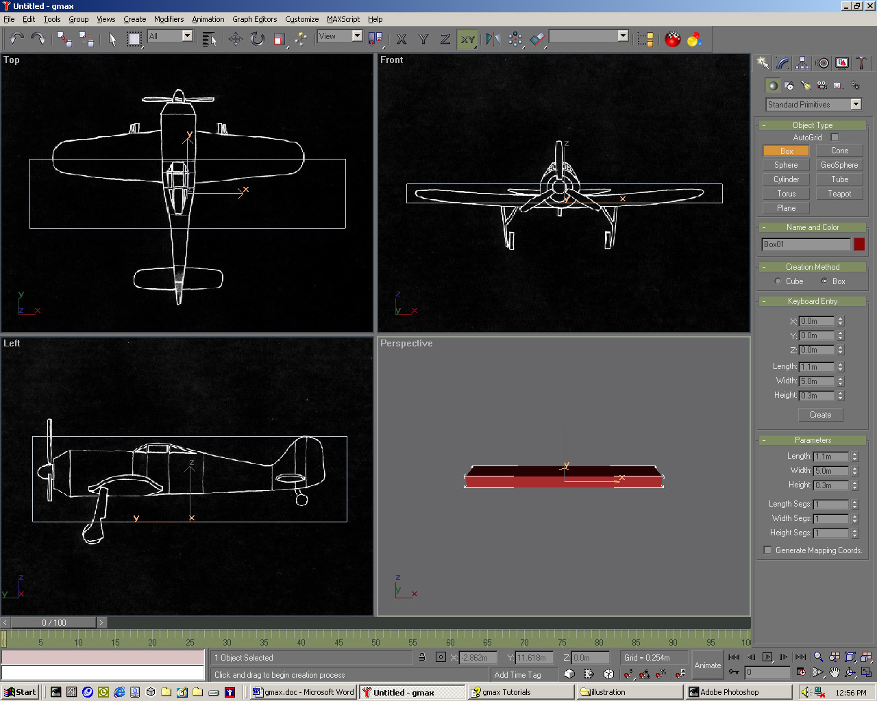 |
| 03 While in the Top viewport press [Alt] + [B] to bring up the Viewport Background dialog again and turn off the Lock Zoom/Pan checkbox. Select the Zoom tool from the same boftom-right corner and zoom in the Top viewport until the width of the box matches the width of the wings, using Pan to centre the box over the image. Repeat for the Front and Left viewports. |
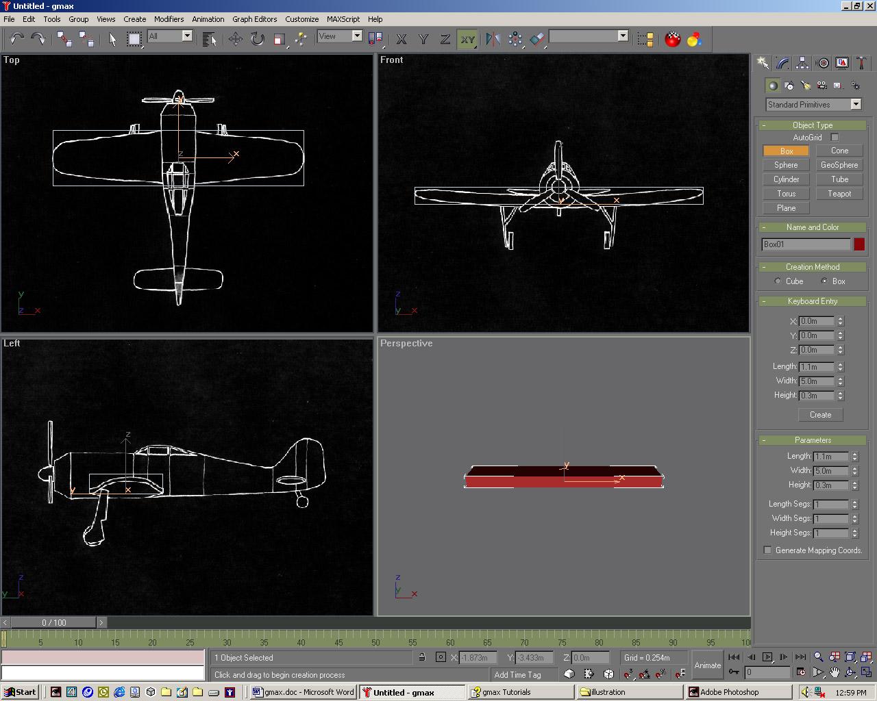 |
| 04 In these three orthogonal viewports press [Ctrl] + [Alt] + [B] to toggle the Lock Zoom/Pan back on. Set the Length, Width and Height to 3, 8 and 1, then right-click and pick Convert to: > Convert to Editable Poly. Add a Taper modifier, with X as the Taper Axis and Y as the Effect. Check Symmetry and drag down on the Amount spinner until the wings match the background.
|
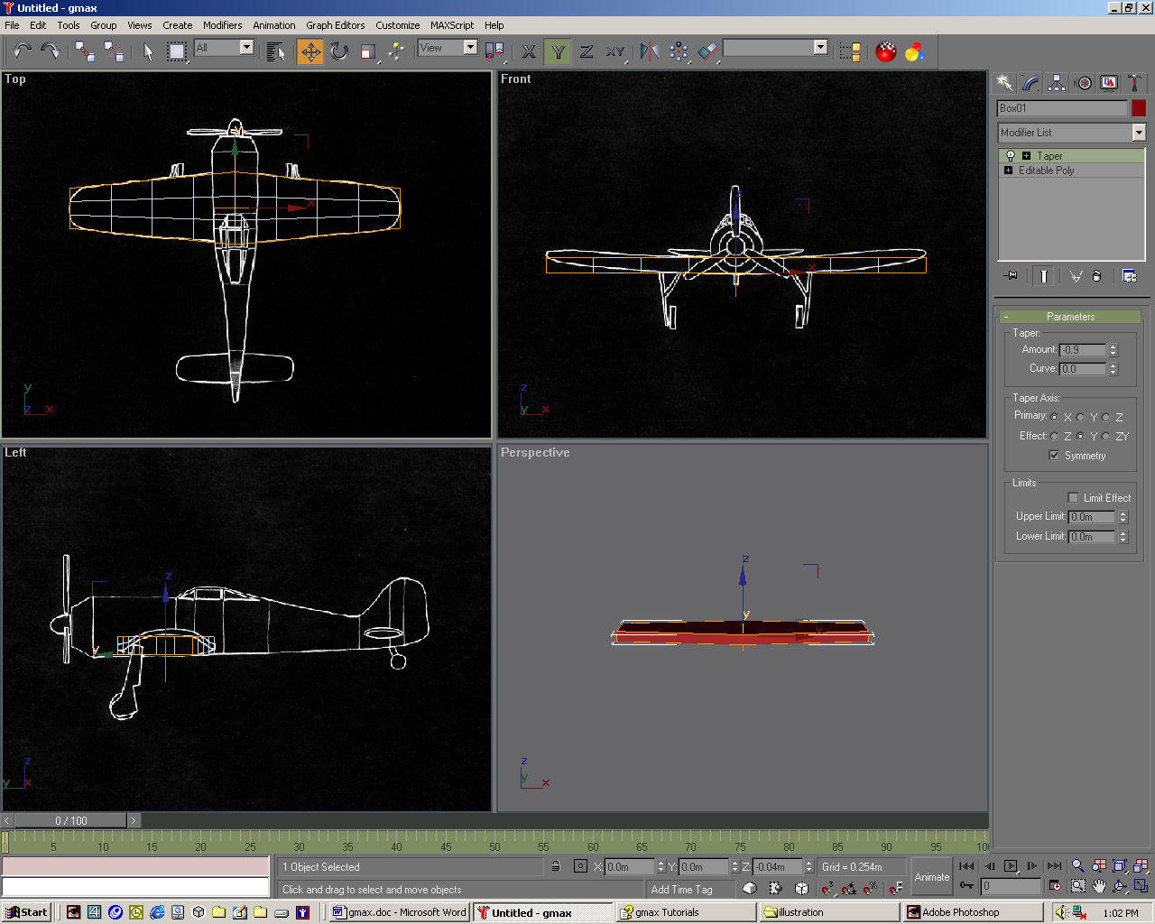 |
| 05 In Center Sub-Object mode, move the centre gizmo tv slightly down until the Taper looks correct. Right-click and convert this again to an Editable Poly. In the Selection rollout on the Command panel click the Vertex icon. Now move the four sets of corner vertices into place, ensuring you drag a selection rectangle to select the vertices directly below the one displayed. |
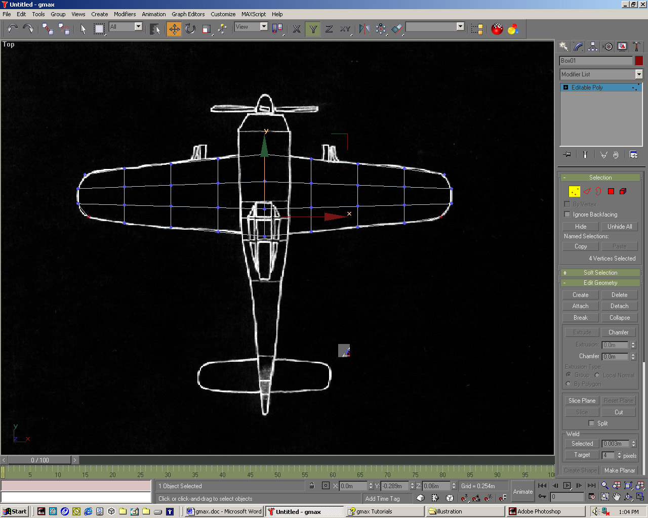 |
| 06 Select all the vertices on the outside edges of the wings. On the main toolbar choose Non-Uniform Scale. In the Front viewport, scale all the edges about the y-axis by dragging over the green arrow, watching the status bar at the bottom of the screen while you scale, and drag until you scale to 30%. Come out of Sub-Object mode and add a Bend modifier.
|
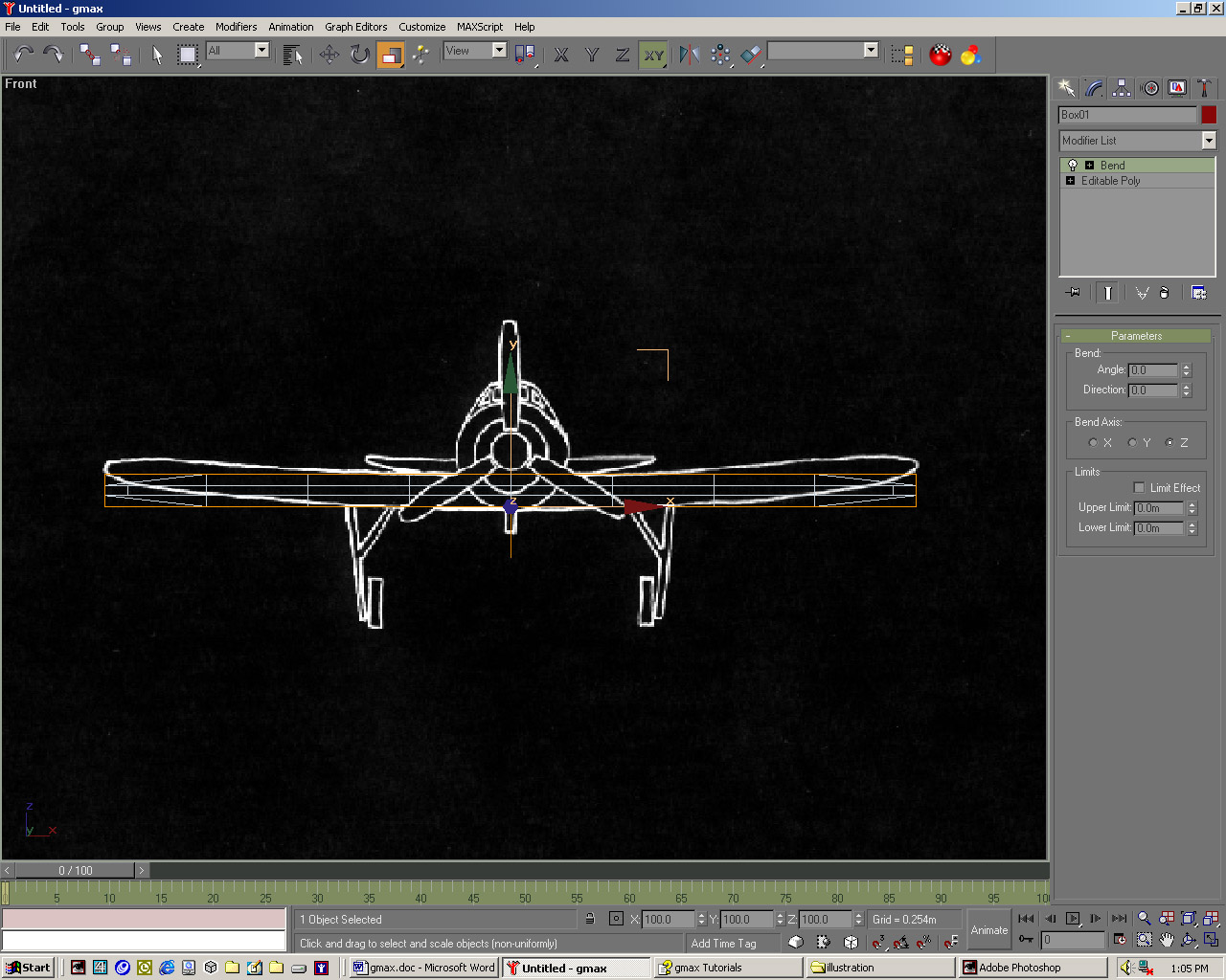 |
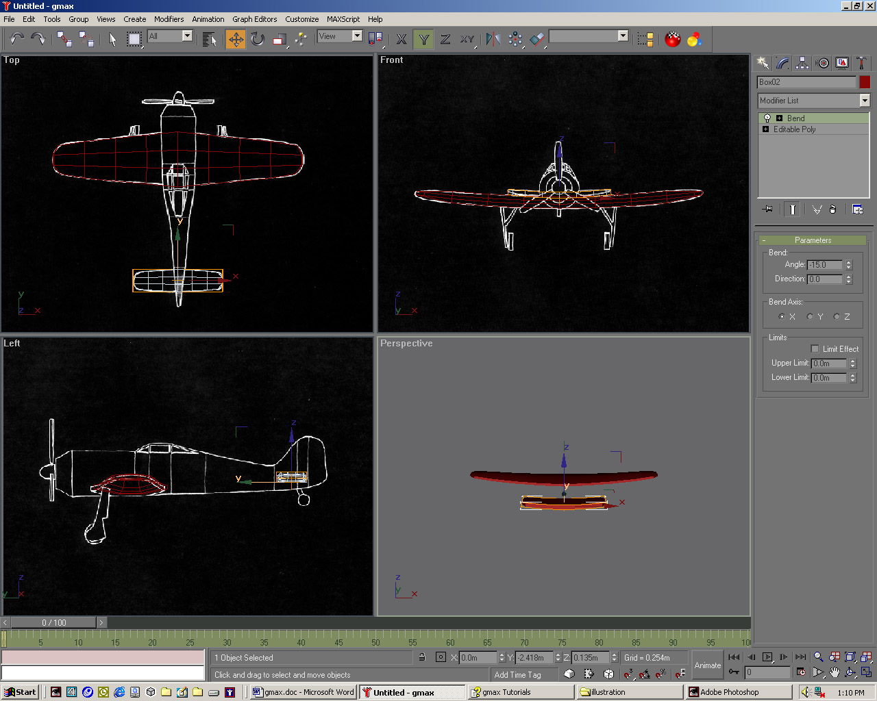
| 07 Set the Bend axis to X and move the Bend Angle spinner until the wings match the Front viewport, which should be around -1 5. You should now attempt to model the tail by repeating steps 5 through 8, though you should begin with a box of 3, 6 and 1 Length, Width and Height segments. In the Front viewport, create a Cylinder centred on the middle of the nose. |
 |
| 08 Give it 9 Height Segments, 1 Cap Segment and 16 sides. Centre it over the fuselage in the Left viewport. Convert it to an Editable Poly object and in Vertex Sub-Object mode, move the seven rows of vertices to line up with the red lines an the background image in the Top viewport. Out of Sub-Object mode, add a Taper modifier so the bottom edge follows the plane image. |
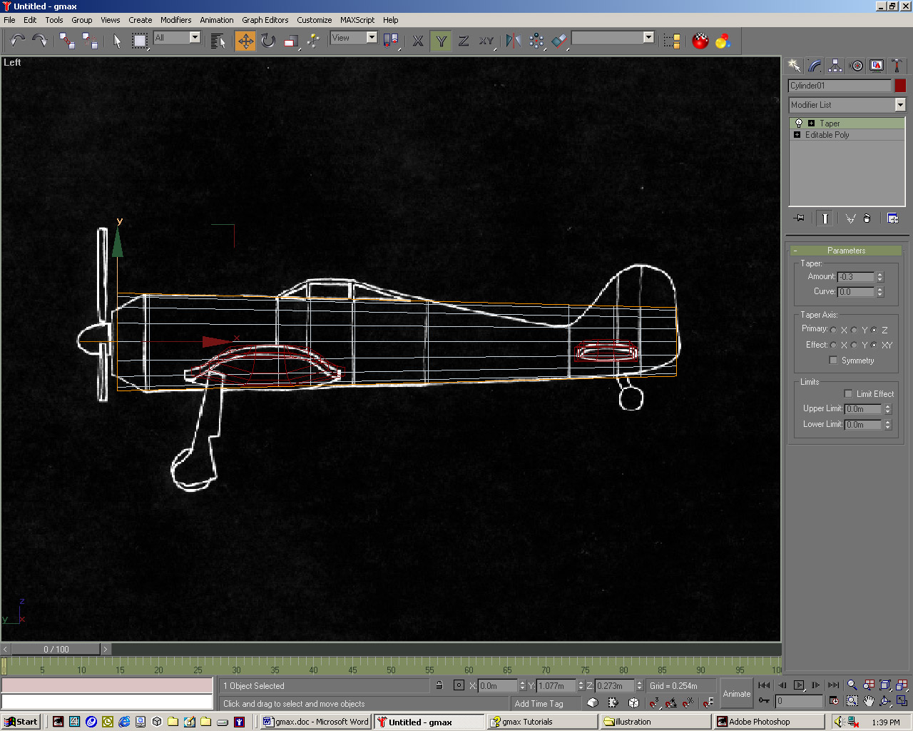 |
| 09 Select the row of vertices nearest to the propeller and using the Uniform Scale tool scale them by around 65% in the Top viewport to fit the background image. For the fifth row onwards, switch to the Non-Uniform Scale tool, and scale along the x-axis only until the rows match the background. Rename the object's wings, tail and fuselage and save as fokkerl.gmax. |
 |